Calculation of Junction Temperature, TJ
Calculation from Lead Temperature and Ambient Temperature
Calculation from Transient Thermal Resistance Characteristics
Thermal Resistance
The following figure shows a conceptual diagram of thermal resistance. The specified position of temperature depends on the package and product.

TJ is junction temperature,
TL is lead temperature,
TA is ambient temperature,
Rth(J-L) is thermal resistance between junction and lead, and
Rth(J-A) is thermal resistance between junction and ambient.
Calculation from Lead Temperature and Ambient Temperature
Junction temperature, TJ is estimated from the measured values of loss and temperature (lead temperature, TL, ambient temperature, TA) during diode operation and the thermal resistance described in the electrical characteristics of the data sheet. TJ is calculated by the following equations.
- Calculation estimating from the lead temperature
- Calculation estimating from the ambient temperature
| TJ = P × Rth(J-L) + TL |
| TJ = P × Rth(J-A) + TA |
Where:
P is the loss of the diode (W),
Rth(J-L) is thermal resistance between junction and lead (°C/W),
Rth(J-A) is thermal resistance between junction and ambient temperature (°C/W),
TL is lead temperature (°C), and
TA is ambient temperature (°C).
As an example, when P = 0.6 W, Rth(J-A) = 20 ° C/W, and TA = 80 °C, TJ is calculated by the following equation.
| TJ = 0.6 × 20 + 80 = 92 (°C) |
Calculation from Transient Thermal Resistance Characteristics
TJ when power is applied instantaneously is estimated from the transient thermal resistance data. TJ is calculated by the following equation.
| TJ = P × rth(J-A) + TA |
Where:
P is the loss of diode (W),
rth(J-A) is transient thermal resistance between junction and ambient temperature (°C/W), and
TA is ambient temperature (°C).
The following figure shows the transient thermal resistance characteristics of SJPZ-N18. For example, when a single square pulse of 100 ms is applied, rth(J-A) is 9 °C/W.

For example, when P = 0.6 W, rth(J-A) = 9 °C/W, and TA = 100 °C, TJ is calculated by the following equation.
| TJ = 0.6 × 9 + 100 = 105.4 (°C) |
Calculation Using Superposition Theorem
This section shows the calculation of the junction temperature, TJ, when a regular square wave power loss occurs in the diode and the junction temperature, TJ, when an irregular square wave power loss occurs in the diode. For such power loss waveforms, it is easy and effective to read the thermal resistance in each period from the transient thermal resistance characteristic graph in the data sheet and use the superposition theorem.
Continuous Pulse
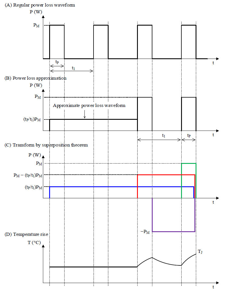
(A) shows the calculation of the junction temperature, TJ, when a regular square wave power loss occurs in the diode. To easily calculate TJ, assume that power losses for two cycles occur in the average power loss over the entire period.
As shown in (B) and (C), TJ is calculated by approximating the power loss and using the superposition theorem.

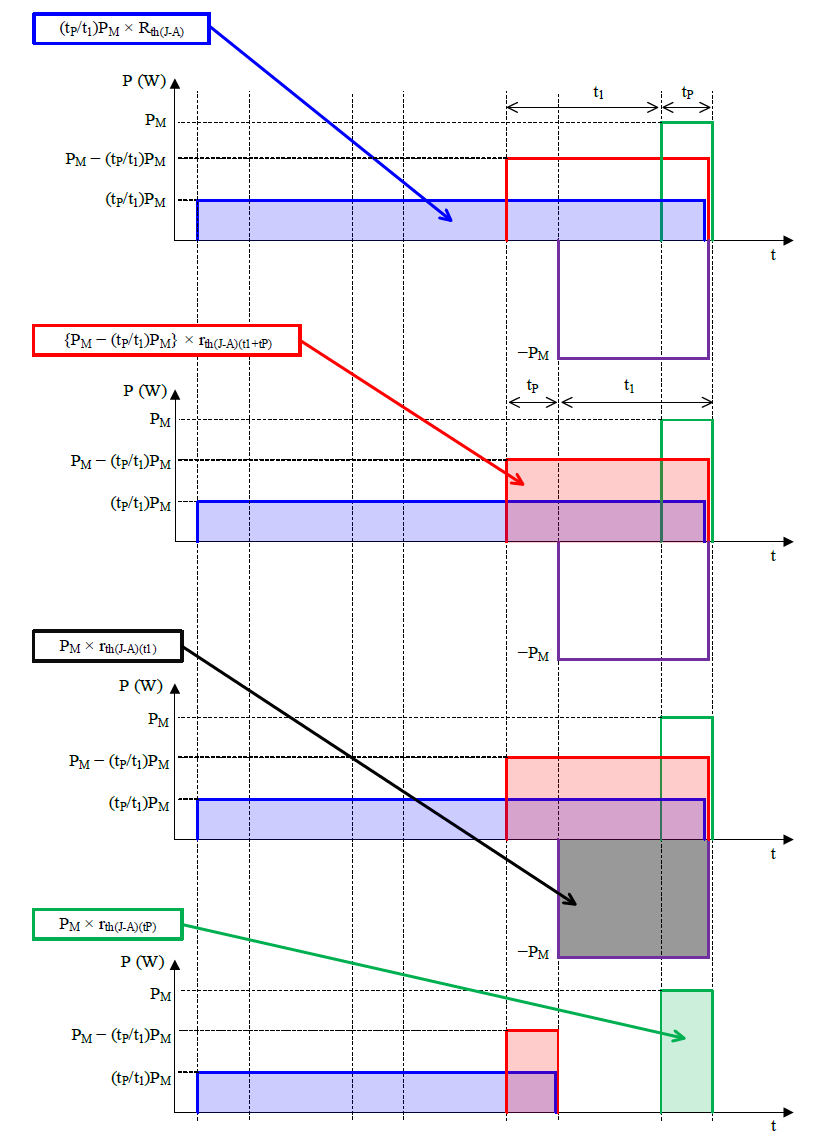
Next, the junction temperature is calculated for each block in (C).

TJ when using the superposition theorem is calculated by the following equation.
 |
Where:
TA is ambient temperature (°C),
PM is average power loss (W),
t1 is period (s),
tP is pulse width (s),
Rth(J-A) is the thermal resistance between junction and ambient temperature in the entire period (°C/W),
rth(J-A)(t1+tP) is the thermal resistance between junction and ambient temperature in the period, t1+tP (°C/W),
rth(J-A)(t1) is the thermal resistance between junction and ambient temperature in the period, t1 (°C/W), and
rth(J-A)(tP) is the thermal resistance between junction and ambient temperature in the period, tP (°C/W).
Irregular Pulse
(A) shows the calculation of the junction temperature, TJ, when an irregular square wave power loss occurs in the diode. As shown in (B), TJ for each block is calculated by using the superposition theorem.

Thus, TJ when using the superposition theorem is calculated by the following equation.
 |
Where:
TA is ambient temperature (°C),
P1 to P3 is power loss for each pulse (W),
rth(J-A)(t6−t1) is the thermal resistance between junction and ambient temperature in the period, t6−t1 (°C/W),
rth(J-A)(t6−t2) is the thermal resistance between junction and ambient temperature in the period, t6−t2 (°C/W),
rth(J-A)(t6−t3) is the thermal resistance between junction and ambient temperature in the period, t6−t3 (°C/W),
rth(J-A)(t6−t4) is the thermal resistance between junction and ambient temperature in the period, t6−t4 (°C/W), and
rth(J-A)(t6−t5) is the thermal resistance between junction and ambient temperature in the period, t6−t5 (°C/W).
Questions or Comments?
Please feel free to contact us if you cannot find the desired product from the lineup.
